 |
SpeakerTalk
This forum has been set up to facilitate discussion of 1970s KEF speakers and drive units. The owner of the Forum has no connection with KEF Audio.
|
| View previous topic :: View next topic |
| Author |
Message |
Nimo_jon
Intermediate Contributor 25+

Joined: 21 Feb 2011
Posts: 48
Location: Singapore
|
 Posted: Mon May 23, 2011 5:07 pm Post subject: KEF 104 to KEF 104aB mkII with SPICE Posted: Mon May 23, 2011 5:07 pm Post subject: KEF 104 to KEF 104aB mkII with SPICE |
 |
|
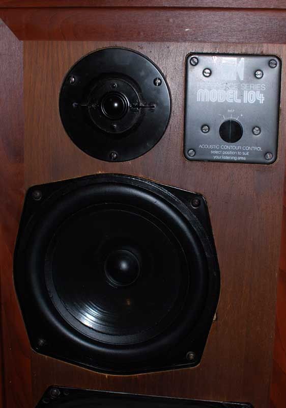
The vintage KEF104 series loud speakers still command a lot of respect today despite its age and simplicity in design. They have been many music lovers’ favorite speakers, and will continue to be much loved.
These 70s speakers have come of age and parts are no longer supported by KEF. If the speakers have spent time in humid conditions, it would require a complete overhaul for sure, after 30years in service. The crossover needs to be checked for component accuracy. And the drivers need to be checked for the correct mechanical and electrical properties.
The crossover’s circuit board traces will have oxidation and corrosion after years of services. On close inspection and measurement, cross over tracks may have become thinner and pose a much higher series resistance in its path. In some cases, the corrosion may have introduced an open circuit.
The old black Elcap black capacitors on the cross over will have to go, even if kept from new. I have measured many of such capacitors. Even good meters usually could not determine the component’s correct values (not less, but strangely, much larger capacitance).
The old Alcap caps may still retain its value after 20 years. Modern capacitors can perform much better. There has been discussion on the series resistances of the cap that affects cross over design. There appear to be two schools of thoughts, and both have their merits.
The simple, small ferrite coils may suffer from hysteresis. At high currents, or fast changing frequencies, any ferrite core will saturate magnetically and cause a non linear departure from the ideal behavior. This will manifest as distortion. The crossovers are placed very close to the driver units (behind the metal plates). Although there could be no significant magnetic coupling path, inductors are best free from strong magnetic fields. (The selector on the KEF face plate introduce contact resistances.)
The internal wiring of these speakers is thin, and made of a few tinned cores. The fact that the crossover sits at the top right of the speaker, to facilitate selection of frequency responses, require a longer wire run. This adds to the current limiting effect of the internal wiring.
As such, the original crossover is best left as is, and a new cross over based on the old design be constructed as replacement. KEF did not put together a speaker crossover from a pile of loose parts. Individual parts must have been measured, put together, and then measured again, to meet a tight specification.
Therefore, to rebuild a crossover, we must at least have a RLC meter, SPICE software to determine the correct modern equivalent for replacement. We need to understand why the crossover was designed that way, and a measurement tool to meet that specification or goal.
Having said that, we may never be able to determine the original design goals KEF had. But KEF certainly had a design budget and there always will be a spread in specification during mass production. This is not building a pair of speakers from scratch, and we can get away from using an expensive full range SPL measuring device.
ORCAD SPICE SIMULATION
This is the original KEF 104 equivalent circuit in SPICE based on KEF’s published driver data sheets. Note that for the passive components during simulation, the inductor is always made up of an inductance and a series resistance (determined by measurements). Inductors have stray capacitance but ignored. Capacitance will have series resistance but ignored. Resistors will have series inductances, but small enough to be ignored.
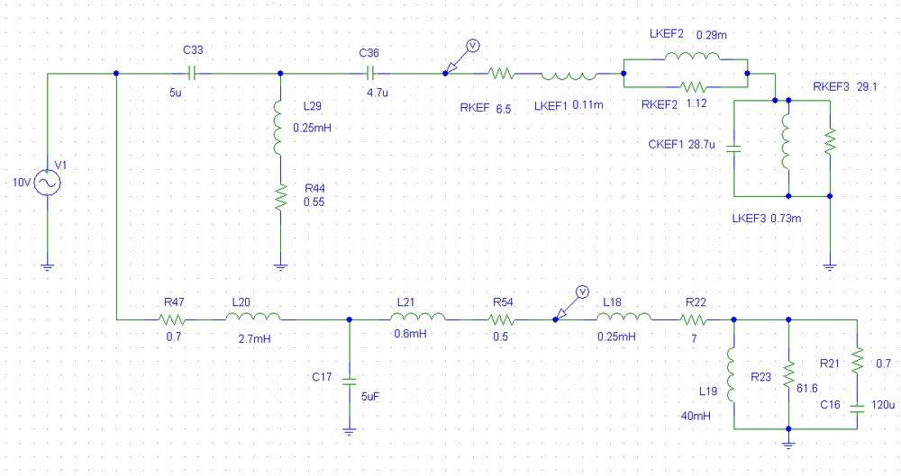
As the simulation is based on the equivalent circuit, this is only an approximation of the actual voltages appearing at the driver’s terminals. This is NOT the actual SPL output of the driver as the driver has its own non linear responses. The simulation studies the electrical characteristics in the frequency domain.
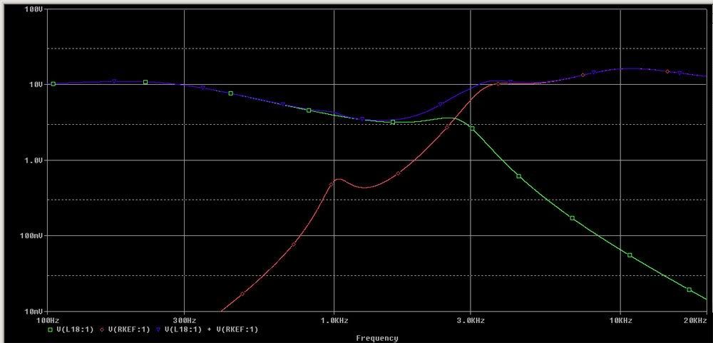
The red trace shows the voltage appearing on the T27 tweeter terminals, and the green trace the voltage appearing at the B200 bass driver terminals. The blue trace shows the summed voltage on the two drivers.
The red trace shows that there is no treatment of the natural resonance at 1.1khz for the T27A driver. There is a very slight hump at the 1kHz summed output (log scale) due to this 'resonance'. This is certainly undesirable.
The green trace shows a kink at the 2.5khz region for the bass driver.
The summed output shows that from 2.5kHz to 3kHz the transition is not smooth. However, the measured SPL of the drivers may be flat (as shown by KEF) due to the non linearity of the drivers.
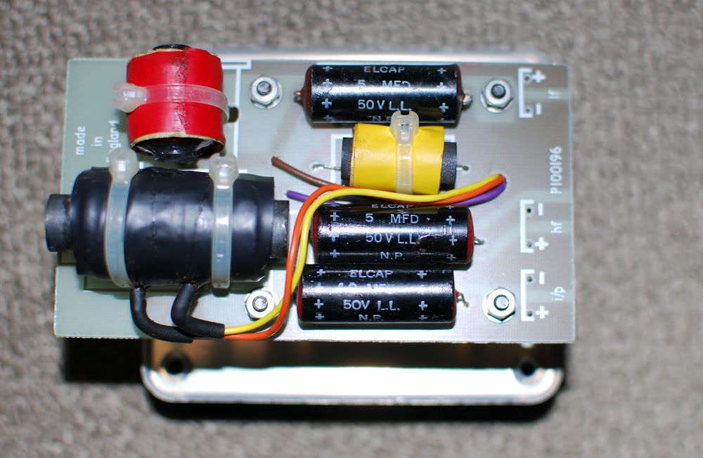
This is the KEF 104aB crossover.
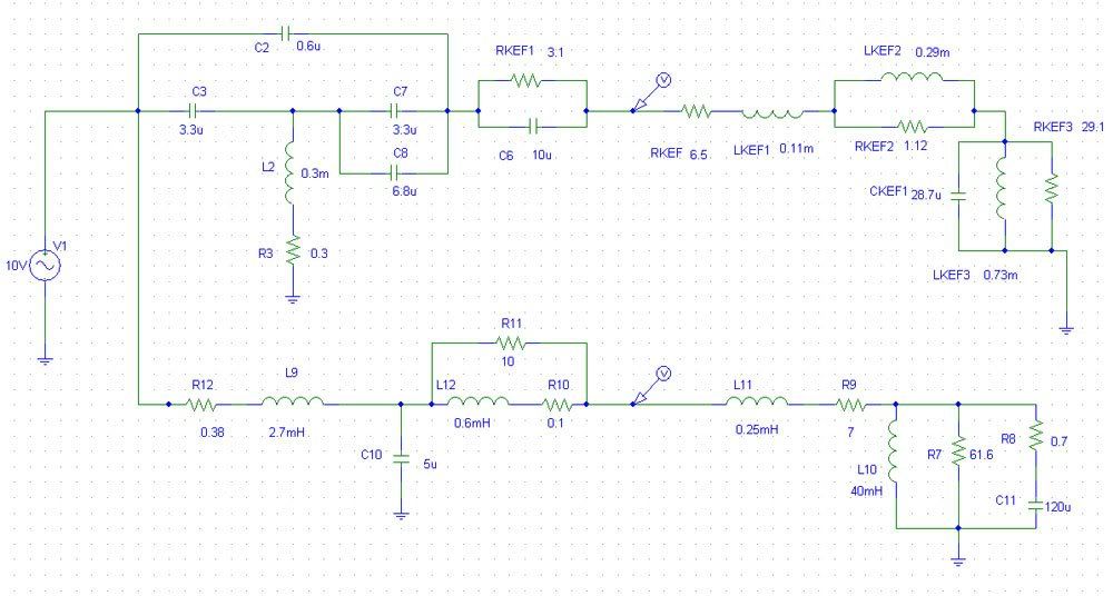
The introduction of a 0.6uf MKT type cap at the high pass, will result in a snubbing effect at the 1.1khz region, thereby attenuates the natural resonances of the T27 driver. The T27 will start to exhibit a falling SPL above the 10khz region, so the introduction of a paralleled 10uf with 3R combo will boost the output above 10khz, and flatten the resultant measured SPL.
As modern caps have lower series resistance (low ESR), this can be compensated by a very small series R, so 3R in the high pass section can be selected to measure 3.1R or 3.2R to retain that damping effect. The value printed on the component may not be the actual value of the component.
The 0.3m inductor is realized by an air cored inductor with only 0.3R dc. The original ferrite core measured 0.55R dc. The resistance of the inductor determines how deep the attenuation of the 1.1khz notch would go. At 0R the attenuation will be close to full attenuation, ie, a short circuit. However, in a real component, there is always some resistance present. It is good to use MKT type for the 0.6uf cap that has a certain series resistance.
The choice of series inductance 2.7mH needs a low series resistance and low magnetic hysteresis. Ideally, an air cored inductor will have the least distortion as there is no core saturation. However, it is hard to find one air core inductor that gives 2.7mH and lower than 0.5R in resistance. The Mundorff Alconit or ferrite series offers a coil at 0.38R with much lower distortion at high current (high current wire).
The 0.6mH is bypassed by a 10R resistor. An air core unit with 0.1R is good choice.
The simulation of the 104aB voltages with consideration of parasitic properties of the components is as follows.
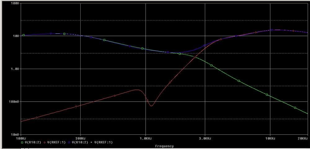
At ~1.1kHz, the voltage is snubbed and prevent the T27a from seeing the offending frequency. Due to the drivers own SPL responses, anything below 1.5khz will have very little output.
At 3kHz the knee kink as in the case of 104, is removed and the transition smoothed. This would make the speaker sound less intrusive.
The B200 transition is also smoothed near the 2-2.5kHz region. The 2.5kHz region determines the perceived sound quality of the speakers.
At 2.5khz, the summed voltages appear to be smooth and no exaggeration between the 2.5khz to above 3khz. This is a marked improvement over the 104 crossover.
The boost above 10khz for the T27 remains. The output is similar to the 104 crossover.
The analysis shows that the KEF 104aB crossover is tweaked to suit the T27a characteristics. KEF's acoustic Butterworth article might not had elaborated much in these technical details. The snubbing effect appears to be a KEF special. This same designs appears in later KEF models such as the Carlton series.
As such, it is not advisable to replace the T27a with any other driver without due consideration of the high pass circuit design. It would be better to source for a pair of used T27a (measured at 6.5ohms dc resistance) than to put in a pair of Seas or Vifa unit (resonant points can be anywhere from 900Hz to 1.2kHz, and different response curves).
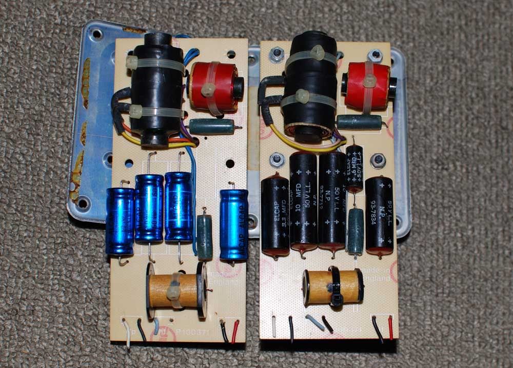
Real World Components
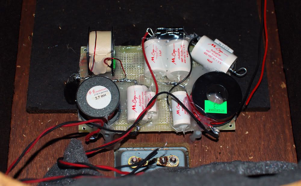
A new cross over is constructed using direct point to point connection of components. Components are secured on a FR4 board using hot glue. The final cross over is also placed near the input terminals, far away from the magnetic field of the speaker drivers.
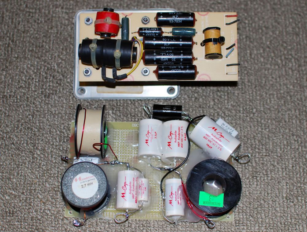
The main inductors can be of the Mundorff cored coil for its low series R and low hysteresis. The other two cores can be air core units but low series R as well. The inductors should be measured to ensure it is within 1% of the value stated.
The capacitors were chose to be Mundorff M caps (400-630V) types. The Mundorff caps are sonically superior to the Solen fast caps; both with a very similar cost. There is no need to bypass each cap with a 0.1 or 0.01uf cap, as this may result in a worse perceived high frequency. Individual caps should be measured for correct values.
The tolerance of the M cap is at 2%, at two extremes the values can be, in the case of 5uf theoretical, be 4.9u against 5.1u. This is not a lot, but we want to be accurate from the start. In the case of 10% tolerances, the deviation could be 4.5u or 5.5u, which will have significant shift in the cross over frequencies.
For internal wiring, it is recommended to use single core 18 or 16 gauge pure copper wires. As the crossover is nearer to the terminals, the overall wire run length is much reduced for the bass driver. The longer wire run for the T27a has little effect, as it favors a slightly higher series resistance. The coil inductance of the driver is much higher than the magnitude of the internal wiring. For the safety of the T27a, the 1 amp fast blow fuse should be in place.
The B200 drivers can still be sourced occasionally on Ebay UK. The drivers should have the same series resistance s and deviate very little from the spec of 7 ohm dc. Due to age, the driver coil may see loose particles in the air gap, or the coil former may be deformed due to heat. This can be checked by slightly depressing the cone and check for rubbing of coil on the magnets. The damaged coil may be repaired, but not many technicians are willing to do it these days.
The bass driver and the passive radiator should have the rubber suspension cleaned and treated by Armor All. The rubber suspension may become dry and brittle in some cases. The change in compliance of the suspension will surely change the sound.
The drivers must be installed with sealing gaskets/foams so that everything is air tight. Check by slightly depressing the main driver, and see a small following excursion on the bass radiator. If the bass radiator do not follow suit, there is leakage.
The new cross over would require at least 100 hours to break in, mainly due to the capacitors. New capacitors will always ‘sound’ closed in, compressed when new. Breaking in over 100 or even 200 hours will significantly improve the sound. Therefore, initial assessment of sound quality when the crossovers are brand new will surely result in a wrong conclusion.
With the new crossover installed with the good drivers, the speakers can sound close to what it was designed for, and even better.
Comparing the original 104 (with new parts) and new 104aB, the mid range is less bloated and high frequency is less piercing, even thought the 104 have higher series resistance caps. Bass is more extended and the speakers sound a few classes higher. The new 104aB sound more refined, fast, detailed and still musical. However, the 104 still holds its charm, mainly due to its coloration which many find it pleasing.
Comparing the original 104aB and the new 104aB, there are more details in the modern version with equivalent sweetness. Bass is less muddled. The speakers appear to have a ‘lower’ sensitivity, as the volume control can be turned a few notches higher. In reality, the speaker can play music louder, with much lesser fatigue to the ears. The most significant difference would be the speed of the speakers. The speaker will be able to handle transients much better. Cymbals and percussion sound more clear but less edgy.
As the crossovers continue to break in with the drivers, sonic spatial illusion becomes wickedly apparent. Separation of individual instruments is improved, and vocals become more life-like. Sound stage layering will be more distinct.
In conclusion, the old caps in these old speakers must be replaced. There is a choice of using the Alcaps, or Mundorff M, depending on personal preferences. The old inductors can be replaced by modern cores that will elevate the performance of the speakers. The internal wires are too thin and relocating the crossovers is advantageous (foregoing the facility of inductance change for equalization).
A new cross over is not expensive to build, and the old crossover can be retained for comparisons, or for display. This is a worthy upgrade; the returns are much greater than buying a new amplifier or even a new pair of modern speakers. |
|
| Back to top |
|
 |
Richie
Senior Contributor 100+

Joined: 06 Nov 2010
Posts: 108
Location: Northamptonshire
|
| Posted: Mon May 23, 2011 7:13 pm Post subject: |
|
|
I have been doing some work on my 104 ab's (on just one), I replaced all the caps with Alcaps (2%) and by passed the contour control and fuse (I don't play them loud). All internal wiring was up graded as were the speaker terminals.
After removing the internal foam (but not the bitchumen pads) I coated the inside of the cabinets with 3mm of flooring grade epoxy resin (does not set quite as hard or go brittle as other epoxy's) I then restored the bass/midrange bracing (mine had become detached probably through wood shrinkage).
I bolted it all back together, I didn't have time to evaluate each component and just did the work on one complete speaker.
I then listened, putting some mono tracks on I began leaping from one chair to the other to try and listen to any differences. There was a slight, tiny improvement, no eureka moment, no jaw dropping and no wow facture. You had to listen very hard and carefully to hear the tiny improvement, I felt the time, money and effort I had put in was not worth it.
However, I did not allow for any 'running in' (as you have said above) and now some 2 months later the worked on speaker is sounding so much better, beginning to sing, and I cant wait to do the other one now.
_________________
Still learning ...... |
|
| Back to top |
|
|
Nimo_jon
Intermediate Contributor 25+
Joined: 21 Feb 2011
Posts: 48
Location: Singapore
|
| Posted: Tue May 24, 2011 4:27 am Post subject: |
|
|
Hello
There is a very quick and dirty way of burning in the components. Use a 9V transformer and connect the caps to the output via crocodile clips. Use a 3.3R in series to prevent over current. The caps will be 'opened up' after a few days.
A better way to break in the speakers would be to run using XLO burn in CD. This would 'treat' the signal wires, speaker cables, and the drivers thoroughly. However, the sound is horrendous. I have heard some guys cover the speakers with blanket and ran the disc on repeat for the whole day:
http://www.amazon.com/XLO-Reference-Test-Burn-Recordings/dp/B0000015AL
For the cabinets, I have attempted wood varnish and also epoxy to stop wood debris from falling off the brace, internals, etc. This is a chip board enclosure... on my other pair of 104aB, I am now applying the real wood veneer. Hope to finish this by this summer.
As mentioned, I would leave the original crossover as is.
If you are replacing the caps, why not consider replacing the ferrite cores as well. The Mundorff Aronit offers a 2,70mH with only 0,25R K59 core. The wire is 1.40mm diameter. Mine is on order and I will use them when they arrive.
Also, moving the crossover far away from the magnetic field of the T27 allows a shorter wire run and ease of installation. This is how crossovers are located in the newer KEF Carlton series.
Yes, I don't play my 104 or 104aB loud too. With the modification done, the speakers sound a lot better. Cheers. |
|
| Back to top |
|
|
Richie
Senior Contributor 100+
Joined: 06 Nov 2010
Posts: 108
Location: Northamptonshire
|
| Posted: Fri May 27, 2011 6:51 pm Post subject: |
|
|
Hi mate, I'm very curious to know if the upgraded ferrite cores make a real difference..... keep us posted.......thanks
_________________
Still learning ...... |
|
| Back to top |
|
|
Nimo_jon
Intermediate Contributor 25+
Joined: 21 Feb 2011
Posts: 48
Location: Singapore
|
| Posted: Sat May 28, 2011 2:24 pm Post subject: |
|
|
Hi mate,
The Mundorff 2.7mH really amazed me after a simple, short run in.
First of all, the mid range has a lot more details, with even more involving sweetness. I could hear my familiar recordings with a lot more air and presence, and yet smooth to the ears. I could 'see' the singer's feet tapping on the floor, or that subtle squeak when he shifted his butt on the chair. This sonic holography was so unreal, but yet so real.
And I was really shocked by the bass in some difficult tracks.
http://www.cduniverse.com/productinfo.asp?pid=7221241
Yes, using only the Naim Nait 5 the bass was marvelous playing tracks like TAKE FIVE. The bass was so deep, firm and fast with control. It was like... playing the KEF 105.2 (?!). But from a 104?
A friend of mine could not believe it after he heard the 104. He thought there was a sub woofer hiding somewhere. He is now embarking on replacing the inductors with Jantzen Pcore inductors.
http://www.parts-express.com/mfg/jantzen/jantzen.cfm
Meanwhile, I am happy with the Mundorff. I heard that a lot of high end speaker manufacturers (those that cost more than a few grand) are using Mundorff parts as well.  |
|
| Back to top |
|
|
mulane
Junior Contributor 10+
Joined: 29 Aug 2011
Posts: 16
Location: Australia
|
| Posted: Mon Aug 29, 2011 1:58 pm Post subject: |
|
|
| Great thread Nimo_jon. Was the modified 104 crossover you used to compare to the modified 104aB crossover the one with Carli Mylar caps which you detailed in your other thread? |
|
| Back to top |
|
|
Nimo_jon
Intermediate Contributor 25+
Joined: 21 Feb 2011
Posts: 48
Location: Singapore
|
| Posted: Mon Aug 29, 2011 2:47 pm Post subject: |
|
|
Hello Mulane,
How you doing? Thanks for reading. Yes the comparison was done with the modified 104. The 104 has moved on to a 104aB.
So now I have TWO pairs of KEF 104aB. Only one pair follows the original design layout (original crossover PCB, original inductors, original Alcaps from England, etc). The other pair is the one presented. From the sound pressure meter both appear to have very similar frequency response, but both demonstrate very different sonic characteristics.
The one with Alcap is alot more forgiving and easy going especially with classical music. The one with MCap can sound a little piercing at times, for old recordings. Depending on my mood, I would let either one pair take the center stage. Recently the ones with Alcap have stayed on a little longer. 
Why not build two crossovers within the same box and implement a switch? Well, I like to keep the circuits simple. Still doing AB comparison, and its hard to make a final decision.  |
|
| Back to top |
|
|
mulane
Junior Contributor 10+
Joined: 29 Aug 2011
Posts: 16
Location: Australia
|
| Posted: Mon Aug 29, 2011 2:57 pm Post subject: |
|
|
So you think the Mundorf M are a better sounding cap for the T27 than the Carli Mylars?
By the way any progress on fitting the Hypwon (?) tweeters in place of the T27s? |
|
| Back to top |
|
|
Nimo_jon
Intermediate Contributor 25+
Joined: 21 Feb 2011
Posts: 48
Location: Singapore
|
|
| Back to top |
|
|
|
|
You cannot post new topics in this forum
You cannot reply to topics in this forum
You cannot edit your posts in this forum
You cannot delete your posts in this forum
You cannot vote in polls in this forum
|
Powered by phpBB © 2001, 2005 phpBB Group
|

